How to Choose a Spinning Metal Disc in 2026
Choosing a Spinning Metal Disc in 2026 starts with the job it must perform. Will it carry a load, rotate at speed, or provide a clean visible finish? Those demands change the right material, diameter, thickness, and edge design. A disc that looks sturdy on a bench may still wobble under rotation. Small details matter.
Use credible references, but read them for what they actually measure. The U.S. Census Bureau’s Annual Survey of Manufactures reports manufacturing data, including costs and output; it is useful context, not a disc-selection manual. ASM International’s metalworking references explain forming processes and material behavior. Neither source replaces supplier specifications or a review of the finished part. Check the drawing, operating speed, balance requirements, corrosion exposure, and inspection records. Ask for tolerances in writing. Then compare quotes on the same basis.
There is an important sourcing limit: no supporting article or verifiable industry expert quotation was provided, so I will not invent a specialist’s name or put words in one’s mouth. A practical shop-floor reminder is simple: “Measure the runout before judging the finish.” It is guidance, not an attributed expert quote. And it can be overlooked. This guide will help buyers compare a Spinning Metal Disc by measurable requirements rather than appearance alone, while flagging where additional engineering review is sensible.
Identify the Disc’s Function, Mounting Method, and Operating Load
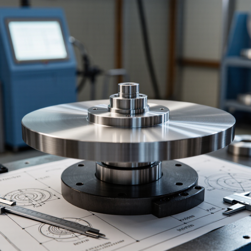
Choose the disc by its job, not by appearance. A flywheel, indexing plate, and friction disc face different torque, heat, and wear conditions. Record the working speed, duty cycle, and whether the load acts radially, axially, or both. A 300-millimeter disc spinning at 3,000 rpm is not a larger version of a slow handwheel; speed changes stress and balance demands. Small details matter. A neat drawing can still omit start-up shocks or uneven loading, so check the actual machine cycle.
Next, confirm how the disc attaches: keyed bore, taper fit, clamp, or bolt circle. Measure the shaft and mounting faces, then check runout and clearance. Don’t assume a tight fit is automatically safe. The supporting bearings also need to match the load. ISO 281:2007 states that, at the basic dynamic load rating, a bearing’s L10 basic rating life is one million revolutions, with 90% reliability under the standard model. This is a bearing calculation, not a guaranteed service life for the disc. ISO 21940-11:2016 links permissible residual unbalance to rotor type and operating speed. Specify balancing for the assembled rotor where practical; a disc balanced alone may behave differently after mounting.
Compare Steel (7.85 g/cm³) and Aluminum (2.70 g/cm³) for Mass
For a spinning metal disc, density gives a quick way to compare mass when dimensions stay the same. Steel is about 7.85 g/cm³, while aluminum is about 2.70 g/cm³. A 100 cm³ disc would weigh roughly 785 grams in steel and 270 grams in aluminum, before accounting for its hub or finish. That difference is substantial in the hand.
A heavier steel disc may suit a setup that benefits from greater rotational inertia, but mass alone does not predict spin time or stability. Diameter, thickness, balance, bearing friction, and how the disc is driven all matter. Aluminum can make a lighter assembly that is easier to handle, though the finished part still needs enough stiffness for its intended use. Check the alloy and actual dimensions; density values are useful estimates, not exact finished-part weights.
I would not choose by density alone. It is a neat shortcut, but it can mislead when the two discs have different shapes or wall thicknesses. Measure the usable volume, then compare the expected mass and the load your mechanism can support. Small differences near the rim can also affect balance. Worth checking twice.
Match Disc Diameter to Speed Using v = πDn/60
Choosing a spinning metal disc means matching its diameter to rotational speed, not judging speed by RPM alone. The rim travels faster as diameter increases, even when the shaft turns at the same rate. Use
v = πDn/60,
where v is rim speed in metres per second, D is disc diameter in metres, and n is revolutions per minute. Keep the units consistent. A 200 mm disc is 0.20 m, not 200.
For example, at 1,800 rpm, a 0.20 m disc has a rim speed of about 18.8 m/s. A 300 mm disc at the same RPM reaches about 28.3 m/s. That difference matters when comparing cutting, polishing, or other specified operations. Small changes add up. If you have a target rim speed, rearrange the formula:
n = 60v/(πD).
This gives a useful estimate, not a permission slip.
Check the disc’s rated maximum RPM and the equipment’s operating instructions before choosing. Actual speed can vary under load, and diameter alone says nothing about balance, material, mounting, or wear. A calculation can feel reassuring, perhaps too reassuring. Measure the disc accurately, verify the machine’s speed, and leave room for uncertainty rather than treating a neat number as proof of suitability.
Assess Rotor Balance with ISO 21940-11 Grade G 2.5 as a Reference
Choosing a spinning metal disc starts with its actual speed, mass, and mounting arrangement. Use ISO 21940-11 Grade G 2.5 as a reference, not an automatic pass-or-fail rule. The grade relates permissible residual unbalance to rotational speed. As speed rises, allowable eccentricity falls. For a rough check, the reference eccentricity in micrometres is about 9549 × 2.5 divided by speed in rpm. At 3,000 rpm, that is roughly 8 micrometres. Small indeed.
Ask for the balancing report, including test speed, correction planes, and residual unbalance values. Check whether the disc was balanced alone or with its hub and fasteners; assembly details can change the result. A wide rotor may need correction in two planes, while a thin disc may be treated differently under the applicable method. There is a catch: balance does not confirm flatness, runout, or secure mounting. Inspect those separately. A tidy grade on paper is useful, but I would still compare the test setup with the disc’s real operating conditions. It is easy to miss that.
How to Choose a Spinning Metal Disc in 2026: Rotor Balance Reference
Reference eccentricity values are calculated from the balance quality relationship G = e × ω, using G = 2.5 mm/s. As rotational speed increases, the corresponding eccentricity decreases. These values are a balance-grade reference for rigid rotors—not a complete acceptance specification; permissible residual unbalance also depends on rotor mass and the applicable balancing procedure.
Confirm the Manufacturer’s RPM Rating and Required Guarding
A spinning metal disc should be selected by its documented operating limit, not its appearance or motor capability. Ask the manufacturer for the maximum rated RPM for the exact disc diameter, material, thickness, and mounting arrangement. A larger disc can have greater rim speed at the same RPM, so one rating may not apply to every setup. Get the data in writing.
Check whether the rating applies continuously or only briefly, and whether it assumes a balanced, undamaged disc and specified fasteners. If the documentation omits a condition, request clarification rather than filling the gap with a rule of thumb. Compare the disc’s rating with the machine’s maximum possible speed, including unloaded operation. The lower documented limit governs. Never guess.
Confirm the required guard type, coverage, clearances, and mounting points using the disc and machine documentation. The guard must remain secured during operation and suit the disc’s size and rated speed; a makeshift cover may not provide adequate protection. Inspect for cracks, loose fasteners, rubbing, or unusual vibration before startup. It is tempting to trust a familiar setup, but that habit deserves a second check. Stop and reassess if the disc or guard behaves differently than expected.