What Is Large Diameter Metal Spinning?
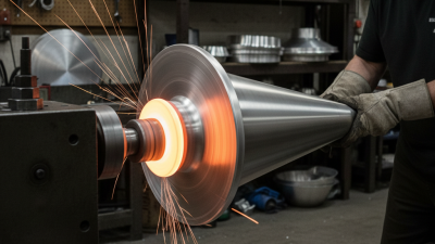
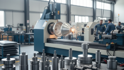
Large Diameter Metal Spinning forms wide metal blanks over a rotating mandrel. A controlled roller gradually shapes the blank into a bowl, cone, dome, or cylindrical component. Unlike ordinary machining, the process changes the material’s geometry while preserving much of its surface continuity. Diameter, wall thickness, alloy, and required tolerances all influence the final result.
Dr. Taylan Altan, a respected sheet-metal-forming authority, has stated, “Sheet metal forming is a highly complex process.” That observation applies strongly to large components. A roller may travel across a stainless-steel blank several meters wide, while small changes in pressure affect thinning, wrinkling, and concentricity. Skilled operators monitor tool alignment, material flow, lubrication, and heat generation throughout the cycle. The work demands experience, not only machine power.
Large Diameter Metal Spinning is used for tanks, aerospace parts, architectural structures, lighting reflectors, and industrial vessels. It can reduce welded seams and produce smooth, continuous surfaces. However, it is not automatically cheaper or more accurate than every alternative. Tooling costs, handling limits, springback, and inspection requirements may change the decision. The process is powerful, but imperfect.
This guide will explain how large-diameter spinning works, which materials suit it, and where quality problems begin. It will also examine equipment, tolerances, surface finish, and production planning. Real results depend on disciplined setup and honest measurement. That part is often underestimated.
Definition and Scope: Forming Rotating Discs Larger Than 1 m
What Is Large Diameter Metal Spinning?
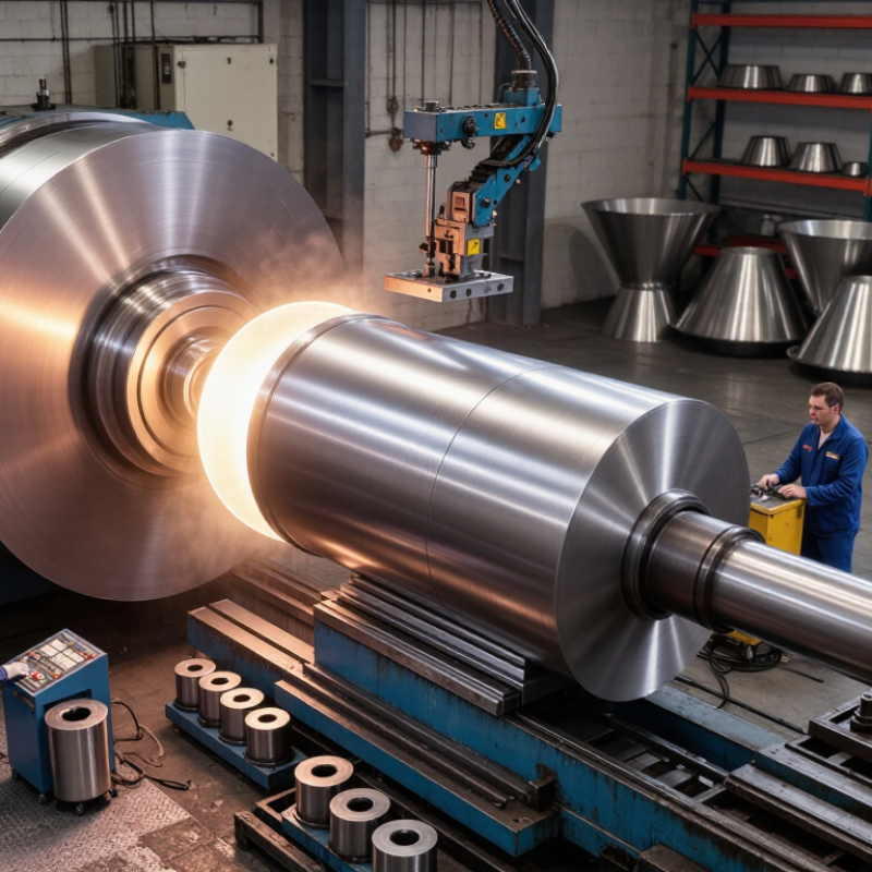
Large diameter metal spinning is a forming process for producing round metal shells, cones, and discs exceeding one metre in diameter. A flat circular blank rotates against a shaped mandrel while a forming tool gradually applies pressure. The metal stretches and flows without being cut away. The 1 m boundary is practical, not absolute. Some workshops use a smaller limit because machine capacity, tooling weight, and handling risks vary.
In production, engineers select aluminium, stainless steel, mild steel, or other ductile metals according to thickness and shape. A large blank may appear simple, but its behaviour changes across the surface. The outer edge moves faster than the centre. Uneven pressure can create wrinkles, thinning, or an oval profile. Experienced operators control feed rate, tool angle, lubrication, and forming passes. Small adjustments matter. Sometimes, the drawing is not enough.
Reliable work depends on more than machine diameter. The mandrel must remain rigid, and the spindle must handle changing loads without excessive vibration. Technicians often inspect the rim, wall thickness, roundness, and surface marks after forming. Laser measurement can help, but direct gauges still reveal practical problems near the edge. A part can meet its diameter target and still fail its fit. This is where process records, material certificates, and repeatable inspection become important. Large diameter spinning is efficient, yet it is not effortless.
Materials and Gauge Selection: Aluminum, Steel, and 0.5–12 mm Stock
What Is Large Diameter Metal Spinning?
Materials and Gauge Selection: Aluminum, Steel, and 0.5–12 mm Stock
Large diameter metal spinning forms a round metal blank over a rotating mandrel. The tool presses and stretches the blank gradually, rather than cutting away most of the material. For wide cones, domes, and housings, material selection affects forming force, surface quality, and final accuracy.
Aluminum is lightweight and responds well to controlled spinning. It suits reflectors, covers, and components where corrosion resistance matters. Softer grades may mark easily under a poorly polished roller. Steel provides greater strength and stiffness, but it needs higher forming pressure and careful lubrication. Stainless steel can resist corrosion, although springback and work hardening may complicate production.
Stock from 0.5 to 12 mm covers very different manufacturing conditions. Thin 0.5–1.5 mm sheet can form efficiently, but it may wrinkle near the flange or distort during trimming. Medium gauges offer a useful balance for general components. Stock above 6 mm often requires stronger equipment, slower passes, and better heat control. Very thick blanks can develop uneven thickness if the tool path is too aggressive.
Diameter matters too. A large blank magnifies small setup errors. Mandrel alignment, blank clamping, and roller pressure must be checked before production. A trial piece is not wasted material. It reveals thinning, cracks, and springback that drawings may not predict. In practice, gauge tables are only starting points. Actual results depend on alloy, temper, diameter, tool radius, and operator control. The most reliable choice comes from testing the real geometry, not guessing from thickness alone.
Process Sequence: Blanking, Clamping, Power Spinning, and Trimming
What Is Large Diameter Metal Spinning?
Large diameter metal spinning shapes a circular metal blank over a rotating mandrel.
The process suits pressure vessels, ducts, reflectors, covers, and other axisymmetric components. Material choice affects forming force, springback, and surface quality.
The International Aluminium Institute reported 70.6 million tonnes of primary aluminium production in 2023. That volume reflects aluminium’s continuing industrial importance, but it does not make every alloy easy to spin.
The Process Sequence
The process sequence starts with blanking. A laser, shear, or punch cuts the disk, while edge quality remains critical. Even a small burr can damage the workpiece during clamping.
The blank is then positioned against the mandrel and secured with controlled pressure. Too little pressure allows slipping. Too much pressure can leave marks.
Power Spinning and Finishing
Power spinning follows.
Mechanized rollers apply force progressively, moving from the center toward the flange. Operators monitor wall thickness, roller angle, feed rate, and heat buildup.
The first pass is often conservative. It should be. Aggressive forming may create wrinkles, cracks, or uneven thinning.
The final operation is trimming, which removes excess material and establishes the required height or edge profile.
ASM International’s ASM Handbook, Volume 14B, emphasizes controlling deformation, tooling, and material behavior during metal forming.
In practice, the sequence is less perfect than diagrams suggest. Measurement after each stage still matters.
Tooling and Quality Control: Typical ±0.5–2 mm Dimensional Tolerance
Large diameter metal spinning forms a flat blank over a rotating mandrel. The process creates cones, cylinders, domes, and transition shapes. For large parts, tooling accuracy strongly influences final dimensions. A small mandrel error can become visible across a wide diameter.
Typical dimensional tolerance is ±0.5–2 mm, depending on diameter, material, thickness, and geometry. ISO 2768-1 tolerance tables list general linear tolerances from ±0.5 mm to ±2.0 mm across larger size ranges. These values provide useful reference points, but they do not guarantee every spun feature. Springback, local thinning, heat, and operator technique can shift results. Real production is less tidy.
Tooling should be measured before forming. Technicians commonly check mandrel diameter, runout, shoulder radii, and mounting alignment.
After spinning, inspectors verify diameter, height, wall thickness, flange position, and roundness. Calipers may support quick checks, while coordinate measuring equipment provides stronger evidence for critical profiles. ASME Y14.5 practices also help define datum references and geometric controls.
A first article inspection should record actual readings, not only pass or fail results. Capability studies can reveal whether a process stays centered inside the tolerance band. NIST’s Engineering Statistics Handbook explains why process spread and centering matter when evaluating capability. One weak point remains: ±0.5 mm may be unrealistic for a very large, thin shell without additional tooling control. Engineers should confirm the tolerance against function, inspection method, and material behavior before production.
Applications and Production Capacity: Reflectors, Tanks, and 1–10 m Parts
What Is Large Diameter Metal Spinning?
Large diameter metal spinning forms round metal blanks over a rotating mandrel. Rollers gradually shape the material into reflectors, covers, cones, and tank components. The process can reduce tooling costs for large parts, especially when designs change during development. It also creates smooth surfaces with fewer welded seams.
Applications and Production Capacity: Reflectors, Tanks, and 1–10 m Parts
Reflectors benefit from accurate circular geometry and controlled wall thickness. They may support lighting, signal, heating, or industrial equipment. Large tanks and vessel sections can also be spun, although pressure applications require separate engineering, inspection, and certification. Specialized equipment may handle diameters from about 1 to 10 meters. That range is not universal. Material grade, thickness, machine power, mandrel design, and workshop handling space all affect real capacity. A 10-meter claim can sound impressive, but it may apply only to thin aluminum or a limited production method.
Tips: Confirm the finished diameter, material, thickness, tolerances, and quantity before requesting a quotation. Ask for sample measurements and a forming plan. Large parts behave differently. Springback, waviness, and local thinning can appear after forming. Measure twice. Engineers should also review lifting points, transport limits, and inspection access. One practical mistake is focusing on diameter alone. A smaller, heavier steel part may demand more planning than a larger aluminum reflector. Contents for tanks must match the material and surface requirements.